


1 引 言
目前,针对农机装备的跟踪控制方法主要有基于数学模型的方法和基于控制理论的方法[6, 7]。其中,数学模型的方法通过农机与参考路径的几何模型计算出农机的期望前轮转角与横摆角速度实现控制,其中以Pure Pursuit算法[8-10]和Stanley算法[11-13]运用较为广泛;基于控制理论的方法主要有线性二次型调节器(Linear Quadratic Regulator, LQR)[14-16],Proportion Integral Differential(PID)[17-19],模型预测控制(Model Predictive Control, MPC)[20-22],模糊逻辑控制(Fuzzy Logic Control)[23]等。
选取无人驾驶滑移转向底盘作为研究对象,与普通的前轮转向底盘相比,采用滑移转向的底盘可以实现小角度的转弯半径,甚至是原地转向和掉头,在丘陵山地等狭窄的作业场景中应用广泛[26]。考虑到底盘在作业场景中会有作业操作人员和其他农业机械存在,容易与底盘产生碰撞,这些外界因素对于底盘来说都是障碍物。为了使底盘能够顺利完成作业,必须在轨迹跟踪的过程中实时躲避参考路径中的障碍物,并顺利回到参考轨迹上。
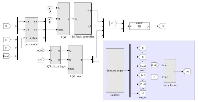
因此,针对无人驾驶滑移转向底盘提出了一种同时实现轨迹跟踪和避障的控制方法。首先,设计了底盘的运动学误差模型。其次,利用T-S(Takagi-Sugeno)模糊模型和并行分布式补偿(Parallel Distributed Compensation, PDC)算法设计了T-S模糊控制器,并对T-S模糊控制器中的每个局部系统都使用了LQR反馈控制器来实现底盘的轨迹跟踪功能。当底盘在面对障碍物时,在全局开环T-S模糊系统中设计了 控制器来进行动态轨迹规划,实现避障控制,并设计了模糊控制器来实时调整其增益矩阵( Q, R )。为了使底盘既能躲避障碍物又不丢失轨迹跟踪的能力,设计了模糊融合控制器将跟踪速度和避障速度联合起来。最后,对该方法进行仿真测试和试验测试。
2 模型设计
2.1 运动学模型设计
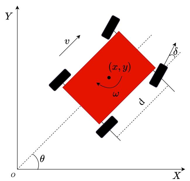
在惯性坐标系XOY下,通过运动的合成与分解可得运动学模型,如公式(1) 所示。
选取[v,w]作为轨迹跟踪的控制量,利用公式(2) :
将公式(1) 转换为公式(3) 的形式:
滑移转向底盘与差速转动类似,将其简化为两轮差速转动机器人,如图2所示。
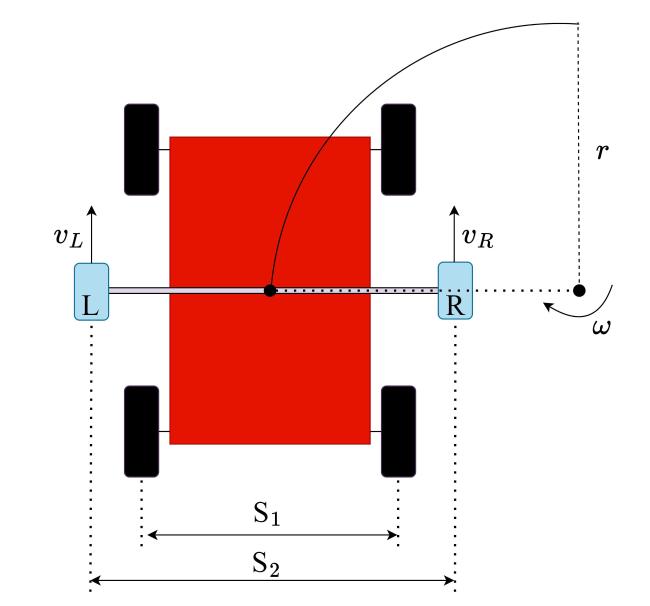
该等效模型以质心和曲率中心为横轴,假设虚拟左右轮的位置位于L点和R点。根据文献[27]中关于滑移转向底盘运动学模型设计的内容,可以得到公式(4) 的等式:
式中: 为虚拟轴距,m; 和 为虚拟左右轮的速度,m/s;r为曲率半径,m。
等效运动学模型是基于底盘的虚拟左右轮进行设计的,其质心处的速度和横摆角速度可以由虚拟左右轮的速度进行计算,如公式(5) 所示。
其逆运动方程为公式(6) :
将公式(5) 带入公式(3) 可以得到基于左右轮速的运动学模型,如公式(7) 所示。
2.2 运动学误差模型设计
为了后续设计控制器,需要将运动学模型中的状态变量设计为底盘与参考路径之间的位置、方向误差。将参考路径中的参考点同样看成一辆底盘,那么这个误差为当前位置底盘与参考路径上底盘之间的误差,如图3所示。
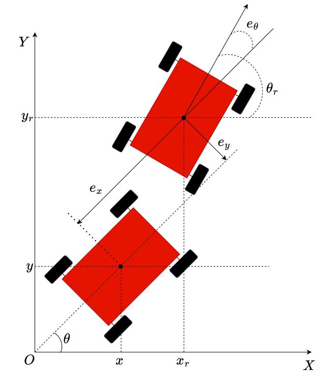
从图3可以得到滑移转向底盘的误差表达式如公式(8) 所示。
式中: , , 为参考位置和航向; , , 为位置误差和航向角误差。联合公式(3) 可以得到运动学误差模型,如公式(9) 所示:
式中: 为参考点的速度,m/s; 为参考点的横摆角速度,rad/s。 u 为控制输入,如公式(10) 所示。
式中: 为系统的前馈控制输入,由参考路径生成; 为反馈控制输入。
联合公式(5) 、公式(9) 和公式(10) 可得公式(11) 所示的滑移转向底盘运动学误差模型表达式。
式中: 分别为参考点的左右轮速度,m/s,由轨迹规划模块提前给出。
对公式(11) 进行线性化操作( ),可得公式(12) 所示的滑移转向底盘运动学误差模型表达式。
式中: e 为底盘状态量的误差矩阵, A 和 B 为系数矩阵。并且当 或 非零时该系统是可控的。 和 在其范围内的不同值可以生成不同的线性误差模型,这些模型可以用来设计T-S模糊模型。
3 轨迹跟踪和避障控制系统设计
底盘的控制系统进行设计主要目的是实现底盘的轨迹跟踪和避障控制。首先设计T-S模糊模型。然后利用PDC算法设计底盘的轨迹跟踪控制器,并且利用LQR控制器获取每个子模块的优化增益。再次,设计 避障控制器,并且该控制器的增益矩阵由一个模糊控制器进行实时调节。最后,通过一个模糊融合控制器将这两个控制器的输出联合起来,形成最终的控制输入。图4为底盘的轨迹跟踪和避障系统控制框图。

3.1 T-S模糊模型
: if ,then:
式中: 为前置变量; 为模糊集;i=1,2,3,…,L;L表示模糊集的序号; ,为状态矩阵和输入矩阵。
全局T-S模糊系统模型如公式(15) 所示。
式中: ; 如公式(16) 所示。
式中: 是 隶属度函数的级数。
令 作为第i次模糊规则的激活方程,公式(15) 可以写为公式(17) 。
对于i=1,2,3,…,L, ,并且该激活函数有公式(18) 所示的凸函数属性。
3.2 PDC算法
: if ,then
式中: 为反馈控制的增益,i=1,2,3,…,L。
通过匹配全局模糊系统,全局T-S模糊控制器可以表示为公式(20) 的形式:
将公式(20) 代入公式(17) 可以得到闭环系统,如公式(21) 所示。
该模糊系统需要满足文献[31]中的稳定性定理,因此,利用MATLAB中的线性矩阵不等式工具箱进行求解(LMI toolbox),计算每个子系统中满足稳定性要求的最优控制律。
3.3 LQR控制器设计
LQR是一种应用广泛的最优控制方法,用于求解给定性能指标的反馈控制系统的最优解,具有最优性、鲁棒性和简单性的特点,目前被广泛应用于自动控制、航空航天、机械工程等领域[32]。根据PDC算法,本节将设计LQR控制器用于计算T-S模糊控制器中的每个子系统的最优解。
由于本研究使用了误差状态空间模型,控制问题表述如下。
控制输入计算如公式(22) :
目标函数计算如公式(23) :
式中:J为目标函数; Q 和 R 为系数矩阵。
线性系统计算如公式(24) :
其中K的组成如公式(25) 所示:
P 为公式(26) 所示的代数Riccati方程的解:
3.4 避障控制器设计
在全局开环系统中设计一个新的 控制器用于实现障碍物的躲避,其实现方法为当系统检测到环境中的障碍物时 控制器开始工作。检测的依据为障碍物与底盘之间的距离,由底盘上的距离传感器获取。若距离低于某个阈值时, 控制器开始工作,实时动态规划出一条无障碍物的局部路径。当底盘上的距离传感器检测到与障碍物之间的距离高于某个阈值时,判定底盘已经成功躲避障碍物, 控制器停止工作。
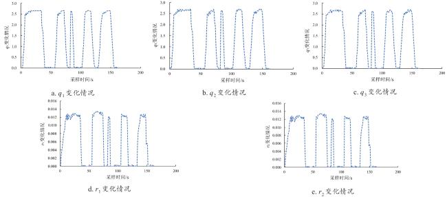
控制器有两个增益矩阵 Q 、 R 的选取决定了 控制器的控制性能。通常这两个参数都是基于设计人员在不断试错中总结出来的固定参数,但往往只适合某些固定的行驶工况,很难适应路径中突然出现障碍物的场景。因此,为了更好实现避障功能,设计了一个模糊控制器,用来实时调节 控制器的增益矩阵 Q 、 R。将获取的距离和底盘的速度作为模糊控制器的输入,模糊控制器的输出为 控制器的增益矩阵( Q, R )的值,从而优化 控制器的输出值,实现更加平滑的避障控制。
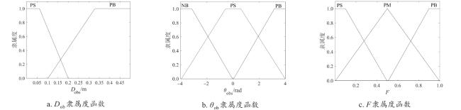
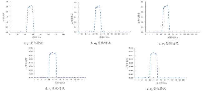
本研究利用一个Mandani模糊控制器来对这两个矩阵参数进行实时调节。该模糊控制器有2个输入,其中一个为当前底盘与参考路径中障碍物之间的距离( ,m),另一个为底盘的速度( )。有5个输出,分别为增益矩阵 Q 的对角元素( )和 R 的对角元素( )。输入(出)变量的基本论域和量化等级如表1所示,其中ZE,PS,PM,PB为用来描述变量的一个区域,分别表示零(Zero, ZE),正小(Positive Small, PS),正中(Positive Medium, PM)和正大(Positive Big, PB)。图5为输入(出)变量的隶属度函数,表2为模糊控制规则,描述了利用逻辑语言来选取增益矩阵的规则,例如:如果障碍物很近(PS),则矩阵 Q 中的 设置为高(PB)实现底盘的快速响应。同时,为了避免快速响应导致底盘失去跟踪稳定性,还需要对矩阵 R 中的 进行调整。如果障碍物很远(PB),则 , 分别设置为0(ZE)和高(PB)让底盘跟踪参考轨迹。
表1 避障控制增益矩阵参数设置Table 1 Parameters setting of gain matrix of the obstacle avoidance. |
| 名称 | 类别 | 基本论域 | 量化等级 |
|---|---|---|---|
| 输入 | [0 m, 0.5 m] | {0 m, 0.25 m, 0.5 m} = {PS, PM, PB} | |
| 输入 | [0 m/s, 1.4 m/s] | {0m/s, 0.4 m/s, 1.4 m/s} = {PS, PM, PB} | |
| 输出 | [0, 3] | {0, 0.4, 1, 3} = {ZE, PS, PM, PB} | |
| 输出 | [0, 3] | {0, 0.4, 1, 3} = {ZE, PS, PM, PB} | |
| 输出 | [0, 3] | {0, 0.5, 0.8, 3} = {ZE, PS, PM, PB} | |
| 输出 | [0, 0.014] | {0, 0.004, 0.006, 0.014} = {ZE, PS, PM, PB} | |
| 输出 | [0, 0.014] | {0, 0.004, 0.006, 0.014} = {ZE, PS, PM, PB} |
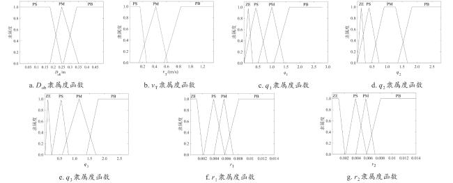
图5 避障控制增益矩阵隶属度函数Fig. 5 Membership function of gain matrix of the obstacle avoidance. |
表2 避障控制增益矩阵模糊控制规则Table 2 Fuzzy rule of gain matrix of the obstacle avoidance |
| 规则数 | 输入 | 输出 | |||||
|---|---|---|---|---|---|---|---|
| 1 | PS | PS | PB | PB | PB | ZE | ZE |
| 2 | PS | PS | PB | PB | PB | PS | PS |
| 3 | PS | PS | PB | PB | PB | PB | PB |
| 4 | PM | PM | PS | PS | PS | PM | PM |
| 5 | PM | PM | PM | PM | PM | PM | PM |
| 6 | PM | PM | PB | PB | PB | PB | PB |
| 7 | PB | PB | ZE | ZE | ZE | PB | PB |
| 8 | PB | PB | ZE | ZE | ZE | PB | PB |
| 9 | PB | PB | ZE | ZE | ZE | PB | PB |
3.5 模糊融合控制器设计
如果在参考轨迹上存在障碍物,底盘必须在跟踪参考轨迹的同时避开这些障碍物。因此,底盘将同时受跟踪速度( , )和避障速度( , )的控制,此时需要设计融合控制器将这两种速度进行融合。本研究选取Mamdani模糊控制器来实现,将输入设置为底盘与障碍物之间的距离 和底盘与障碍物之间的角度 ,其中 的论域为[-4rad, 4 rad],量化等级为{-4 rad, 0 rad, 4 rad}={NB, PS, PB},其中NB为用来描述变量的一个区域,表示负大(Negative Big, NB)。输出为融合增益F,论域为[0, 1],量化等级为{0,0.5,1}={PS,PM,PB}。输入(出)隶属度函数如图6所示,融合增益的模糊规则如表3所示,描述了利用逻辑语言来选取融合增益的规则,例如:如果障碍物很近(PS),障碍物与底盘之间的角度偏大(PB),则F设置为高(PB),增加最终输入值中避障速度的比重,让底盘快速躲避障碍物。如果障碍物很远(PB),则F设置为低(PS),让底盘跟踪参考路径。
由上述模糊融合控制器可以得到底盘最终的控制输入如公式(25) 所示。
4 仿真测试
为了验证本研究所提避障控制方法的有效性和正确性,在MATLAB/Simulink中进行联合仿真测试。
4.1 仿真环境
表4 滑移转向底盘参数Table 4 Parameters of the skid-steering chassis |
| 参数名称 | 单位 | 数值 |
|---|---|---|
| 整机形式 | / | 轮式 |
| 外形尺寸 | mm | 1 500×1200×800 |
| 装备质量 | kg | 200 |
| 载重 | kg | 100 |
| 平均最高车速 | km/h | 5 |
| 轴距 | mm | 800 |
| 轮距 | mm | 1 100 |
| 虚拟轴距 | mm | 1 250 |
| LQR增益矩阵 Q | / | diag(1,1,1) |
| LQR增益矩阵 R | / | diag(0.005,0.005) |
4.2 仿真设计
设计了如图8所示的Matlab-simulink联合仿真实验。
4.3 仿真结果分析

图9 底盘无障碍物时的跟踪结果(仿真)Fig. 9 Tracking results of chassis without obstacles (simulation) |
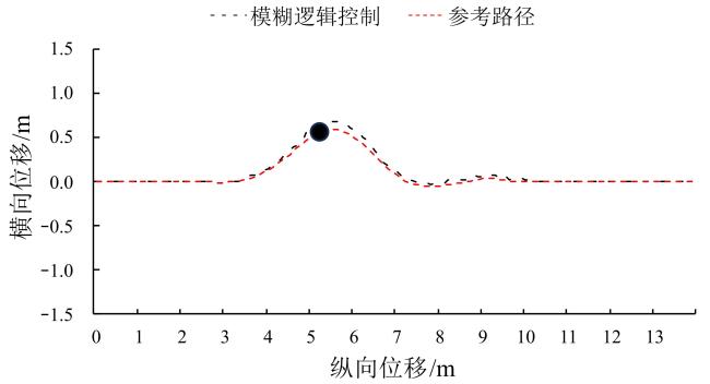
图10 底盘有障碍物时的跟踪结果(仿真)Fig.10 The tracking results of chassis with obstacles (simulation) |
表5 不同工况下的仿真结果对比Table 5 Comparison of simulation results under different working conditions |
| 工况 | 横向平均跟踪误差/m | 纵向平均跟踪误差/m | 直线平均横向跟踪误差/m | 直线平均纵向跟踪误差/m | 曲线平均横向跟踪误差/m | 曲线平均纵向跟踪误差/m |
|---|---|---|---|---|---|---|
| 无障碍物 | 0.036 5 | 0.048 2 | 0.021 | 0.030 | 0.065 | 0.078 |
| 有障碍物 | 0.189 | 0.223 | 0.023 | 0.028 | 0.532 | 0.489 |
5 试验测试
5.1 试验平台
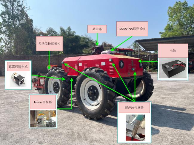
为了验证该方法的有效性,将该方法部署在自主研制的农用电动滑移转向底盘上进行试验测试,如图12所示。底盘的驱动方式为滑移转向驱动,由两个伺服直流电机带动链条进行驱动。配备了英伟达Jeston Nano 控制主板,五个倍加福超声波传感器(分别位于正前、左前、右前、左后、右后),全球导航卫星系统(Global Navigation Satellite System, GNSS),惯性导航系统(Inertial Navigation System, INS)等设备。其中伺服电机的额定功率1000 w、额定转速3000 r/min、额定转矩3200 N·m,同时直流伺服电机自带双驱伺服控制器,支持电机数据的读取。
采用机器人操作系统(Robot Operating System, ROS)进行试验验证。利用五个倍加福(Pepperl-Fuchs)超声波传感器检测障碍物的位置,可以实现毫米精度的检测。利用超声波传感器自带的同步输入功能可以实现五个传感器之间以内轮循同步的方式发射超声脉冲,实现五个传感器的并行操作。利用GNSS/INS惯导系统获取底盘的位置信息和横(纵)向的加速度信息。利用直流伺服电机自带的反馈元件获取电机的转速和底盘的速度信息。
5.2 试验设计
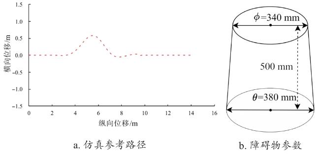
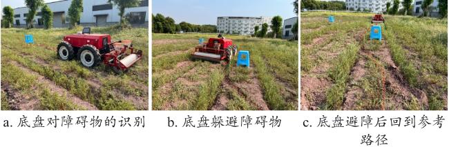
底盘可以用于农业作业中的播种、除草、施药、覆膜等一系列作业,选取图13所示的试验场景,用于模拟播种和覆膜作业场景。该作业场景中包括了直行、掉头、转弯等常见农业作业路径。
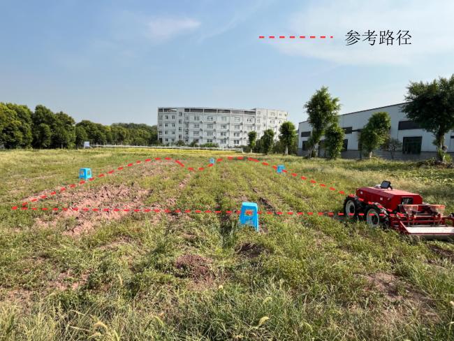
对该路径进行加载和预处理,可以得到图14所示的参考路径。路径中的黑点表示路径中的障碍物,共设置了4个障碍物。
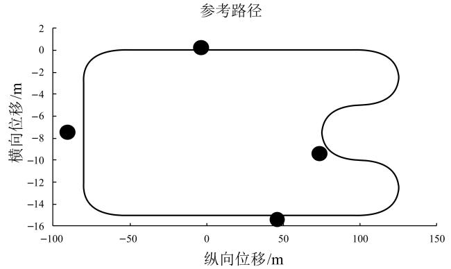
为了验证 +模糊控制器的有效性,试验测试中将加入增益矩阵固定的 控制器进行对比,固定增益矩阵的值为: Q =diag(1,1,1), R =diag(0.015,0.015)。
5.3 试验结果与分析

图15 底盘无障碍物时的跟踪结果(试验)Fig.15 Tracking results of chassis without obstacles (experiments) |
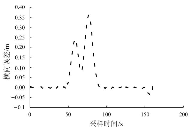
图16 底盘无障碍物时的横向跟踪误差(试验)Fig. 16 Lateral tracking error of chassis without obstacles (experiments) |
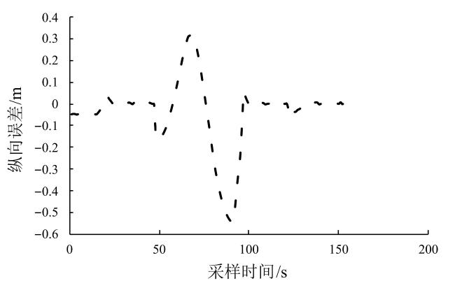
无障碍物时,底盘横纵向平均跟踪误差分别为0.041和0.052 m,弯道处的横纵向平均跟踪误差分别为0.131和0.352 m,处于可以接受范围之内(小于0.6 m)[24]。
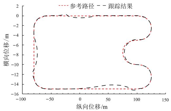
图18 搭载模糊避障控制器的底盘避障跟踪结果(试验)Fig. 18 Obstacle avoidance and tracking results of chassis with fuzzy obstacle avoidance controller (experiments) |
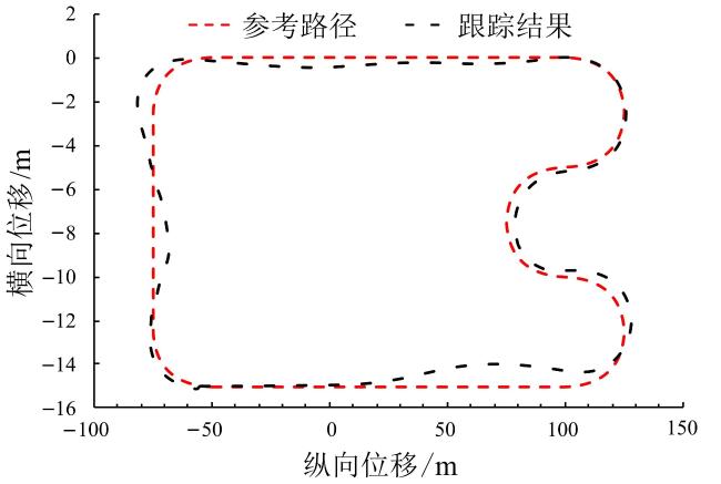
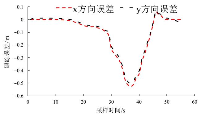
以上试验结果表明,在没有障碍物时,农机底盘可以利用T-S模糊控制器实现对参考轨迹的跟踪,整个跟踪过程横纵向的平均误差分别为0.041和0.052 m。在面对障碍时,T-S模糊控制器和 控制器通过联合控制可以同时实现底盘的避障和跟踪控制。设计的模糊控制器可以对 控制器的增益矩阵进行动态调整,跟踪误差相较于固定增益矩阵的控制器降低了33.9%。
6 总 结
轨迹跟踪和避障控制是自动驾驶底盘的重要组成部分,但目前大多数研究将这两个问题作为两个独立的任务来完成,这将导致底盘在面对障碍物时需要先停止轨迹跟踪,完成避障之后再次实现轨迹跟踪,如果避障后距离参考路径太远则会影响后续的跟踪效果。目前也有一些轨迹跟踪和避障同时进行的研究,但这些研究要么不够平滑容易出现抖动现象,要么控制系统太过复杂。本研究则提出了一种基于模糊逻辑控制的方法来同时解决轨迹跟踪和避障控制问题。通过设计底盘的运动学模型和运动学误差模型获取T-S模糊模型。基于T-S模糊模型利用PDC算法设计了T-S模糊控制器,利用LQR作为其每个子系统的反馈控制器用于实现底盘的轨迹跟踪。在全局开环控制器中又设计了一个新的 控制器实现动态轨迹规划,实现避障,并且该控制器的增益矩阵由一个模糊控制器进行实时动态调整。设计了模糊融合控制器来将T-S模糊控制器和 控制器结合起来形成底盘最终的速度输入。利用了MATLAB-Simulink对该控制方法进行联合仿真验证,并将该方法部署到自研的农用滑移转向底盘中进行试验测试,结果表明,该方法能够在轨迹跟踪的同时实现避障控制,并且控制系统简洁高效;避障后可以快速地将跟踪误差收敛到零,实现更加平滑的避障控制。设计的模糊控制器可以动态调整 控制器的增益矩阵,相较于不采用模糊控制器的控制方法,该方法的整体控制精度提高了33.9%。
提出的基于模糊算法的跟踪避障控制方法简洁高效,能够同时实现底盘的轨迹跟踪和避障控制,跟踪和避障效果显著。但目前该控制方法还只能处理参考路径中的静态障碍物,后续将针对动态障碍物进行研究。


